
Oct 13, 2026Testing Standards
EMC Radiated-Emission Test Distances: Why Laboratories Use 1 m, 3 m, and 10 m — and How Limit Conversion Actually Works
Why EMC labs use 1 m, 3 m and 10 m setups, when 20log10(d1/d2) conversion is valid, and how CISPR and FCC radiated limits relate across distances.
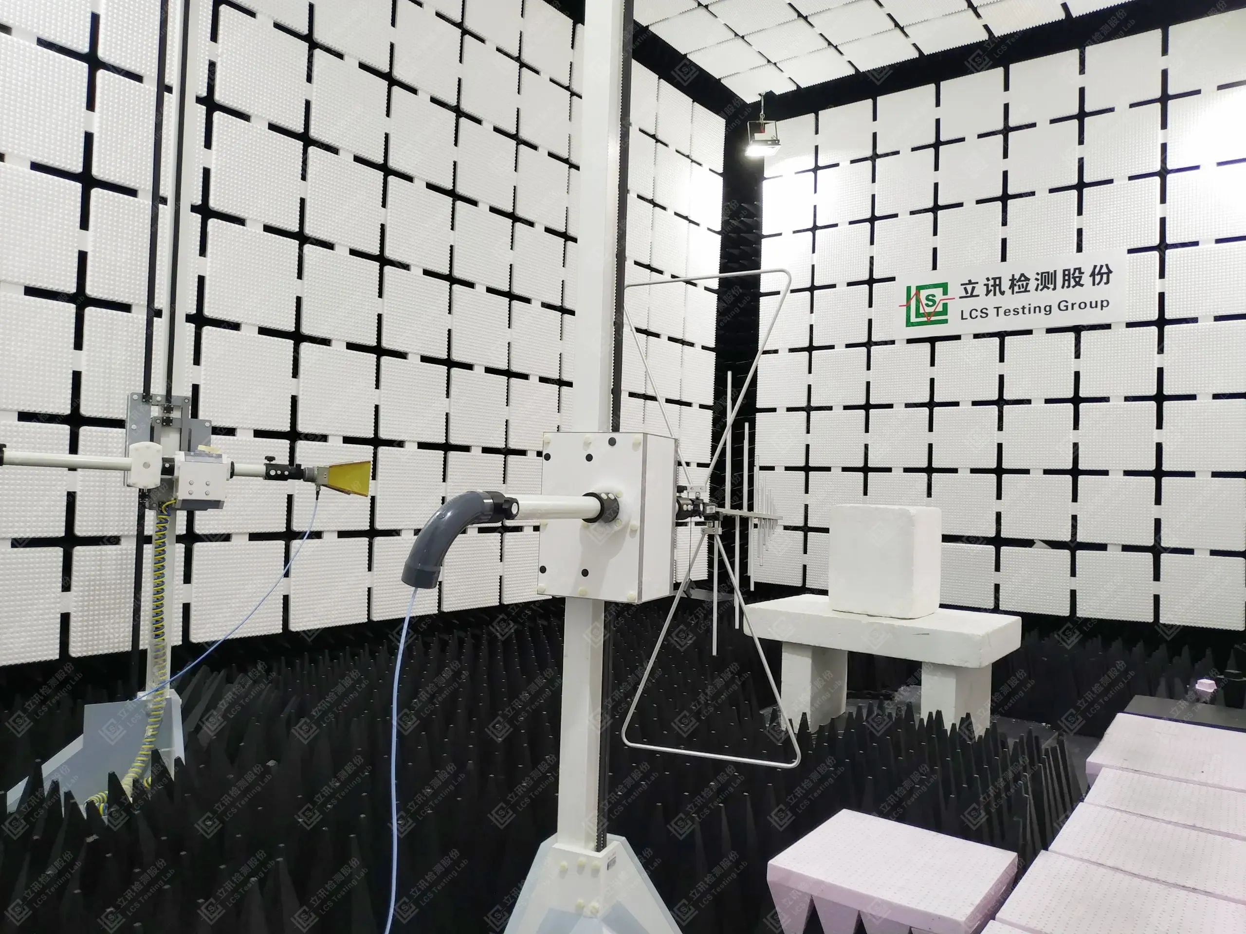
Why the same product has three different "limits"
A radiated-emission measurement is a chain: the equipment under test (EUT) radiates, the wave propagates, a calibrated antenna captures it, and a receiver reports the result in dBµV/m. Because field strength falls with distance, the number is meaningful only with the distance attached: 40 dBµV/m at 3 m becomes roughly 20 dB less at 30 m.
Standards therefore fix reference distances, balancing physics against test volume. A 10 m path needs a room roughly three times the length of a 3 m path and costs several times more to build and run; a 1 m path fits a small screened room but may place the antenna inside the near field of many EUTs at lower frequencies. That is why 1 m is used where a standard defines the geometry — MIL-STD-461 RE102 is measured at 1 m, and automotive CISPR 25 testing uses an absorber-lined shielded enclosure (ALSE) built around a 1 m antenna-to-EUT distance. The distances are not interchangeable by preference; each standards family wrote limits around one.
The far-field relationship behind every conversion
Distance conversion rests on far-field propagation: electric field strength decays as E ∝ 1/r, so E₂ = E₁ × (d₁/d₂). Field strength is an amplitude quantity, so the decibel form uses 20·log₁₀:
L₂ = L₁ + 20·log₁₀(d₁/d₂)
A tenfold increase in distance therefore costs 20 dB. The 10·log₁₀ factor belongs to power quantities, whose density falls as 1/r² — hence "20 log" for field strength.
Far field is a condition, not a given
The far field is bounded by geometry. Three conditions should hold: r ≫ λ (many wavelengths from the source), r ≫ D (D = largest source dimension), and r > 2D²/λ, the Fraunhofer distance. The reactive near field extends to about λ/2π ≈ 0.159λ; between λ/2π and 2D²/λ lies the radiating near field (Fresnel). Amplitudes fall as 1/r³ (reactive), 1/r² (Fresnel), and 1/r only in the far field — the region where 20·log₁₀ conversion is trustworthy.
Concrete numbers: at 30 MHz, λ ≈ 9.99 m and λ/2π ≈ 1.59 m, so 3 m sits just outside the reactive boundary but only 0.3λ from the source; at 10 MHz, λ/2π ≈ 4.8 m, so 3 m is inside the reactive near field. At 1 GHz, λ/2π ≈ 4.8 cm, but the Fraunhofer distance for a 1 m aperture is 2D²/λ ≈ 6.7 m — even 3 m can sit inside 2D²/λ for a large EUT. Hence standards fix distance, antenna, and method rather than relying on point-source theory, and below 30 MHz (λ/2π ≈ 47.7 m at 1 MHz) regulators use a 30 m reference with a different extrapolation slope.
The conversion table, reproduced
With the direction "reference distance → measurement distance," a limit at a closer distance is numerically higher:
Conversion: 10 m → 3 m; Limit change: +10.46 dB; Formula: 20·log₁₀(10/3) = 10.4576
Conversion: 3 m → 1 m; Limit change: +9.54 dB; Formula: 20·log₁₀(3/1) = 9.5424
Conversion: 10 m → 1 m; Limit change: +20.00 dB; Formula: 20·log₁₀(10/1) = 20.0000
The reverse directions use the same magnitudes with the sign flipped. Worked example: a limit of 30.0 dBµV/m at 10 m corresponds to 30.0 + 10.46 = 40.46 dBµV/m at 3 m. The exact factor is 10.46 dB; 10.5 dB is the rounded value. The steps differ — 9.54 dB for 1 m → 3 m versus 10.46 dB for 3 m → 10 m — because the ratios differ.
Standards bake this in differently. CISPR 32 / EN 55032 uses a flat 10 dB: Class B limits are 30 and 37 dBµV/m at 10 m versus 40 and 47 dBµV/m at 3 m (30–230 MHz and 230–1000 MHz) — a nominal step, not the exact 10.46 dB. The FCC rules use a slope instead: 47 CFR 15.31(f)(1) requires measurements at other distances (permitted at or above 30 MHz when not in the near field) to be extrapolated using 20 dB/decade. Section 15.109(g)(2) gives a worked example: above 1000 MHz, a Class B limit is 500 µV/m (54.0 dBµV/m) at 3 m and 150 µV/m (43.5 dBµV/m) at 10 m — a ratio of 3.333, i.e. 10.46 dB. The 20 dB peak-above-average allowance of §15.35(b) reproduces the familiar 74/54 dBµV/m peak/average pair.
Which rule specifies which distance
CISPR 32 / EN 55032 (multimedia equipment; successor to EN 55022; methods per CISPR 16-2-3): limits are defined at 10 m with a matching 3 m set, and above 1 GHz peak/average limits are commonly applied at 3 m. Both distances are options inside one standard.
FCC Part 15: §15.109(a) sets 3 m limits (100/150/200/500 µV/m) for unintentional radiators other than Class A digital devices; §15.109(b) sets 10 m limits for Class A (90/150/210/300 µV/m); §15.209(a) uses 3 m above 30 MHz and a 30 m reference below. Other distances are permitted under §15.31(f): 20 dB/decade at or above 30 MHz; below 30 MHz, a two-distance measurement or 40 dB/decade extrapolation.
MIL-STD-461 (RE102) and CISPR 25 (automotive components): built around 1 m in their own defined rooms — not conversions of a 10 m limit, but separate geometries with their own limit lines.
What actually changes between the setups
Chamber size and cost. A 10 m semi-anechoic chamber must fit the full antenna-to-EUT path plus clearance and absorbers — several times the volume of a typical 3 m room.
How the distance is defined. Under FCC §15.31(f), distance runs from the antenna to the closest point of the EUT, support equipment, or cables, bounded by an imaginary straight-line periphery — so cable routing changes the official distance.
Antennas and band. Biconical antennas cover the lower bands, log-periodic or hybrid bilog antennas the higher bands below 1 GHz, and double-ridged horns above 1 GHz — each with a different phase center and beam pattern.
Ground reflection and height scanning. Direct and reflected rays can add; ITU-R SM.329 notes a maximum field of about 1.6 times the free-space value, roughly 4 dB, which height scanning captures.
Site validation. Each distance has its own validation requirements; a validated 3 m room says nothing about 10 m.
Reading conversions correctly
Distance conversion has three legitimate uses: when a standard allows it (FCC §15.31(f), or CISPR alternative distances), convert exactly as specified and document the method; for cross-laboratory comparison, normalize only alongside site validation results, uncertainty, and identical layouts; and for pre-scan or debug work, where normalizing a 3 m sweep to 10 m expectations helps prioritize fixes — while compliance still requires a formal test at the required distance.
The trap is treating mathematically valid conversion as blanket substitution: the 20·log₁₀ relationship assumes far-field propagation from an idealized source. Real EUTs radiate from cables and structural resonances, low-frequency measurements may sit in the near field, and chamber reflections, EUT size, and antenna behavior add spread. Mathematically convertible does not mean standard-permitted, and standard-permitted does not mean the measured value can be predicted to the decibel. When a customer requires a 10 m test and only a 3 m room is available, ask whether the standard permits 3 m, whether a minimum distance is specified, whether the site meets its validation requirements, and whether the EUT fits the method — not simply "add 10.46 dB."
LCS's EMC laboratory in Shenzhen tests emissions and immunity across CISPR, EN, and FCC frameworks; confirm specific test configurations and applicable limit lines with the laboratory before planning.